CPU Card Interface Connectors
|
Key to CPU card interface connectors |
|
|---|---|
|
Feature |
Description |
|
|
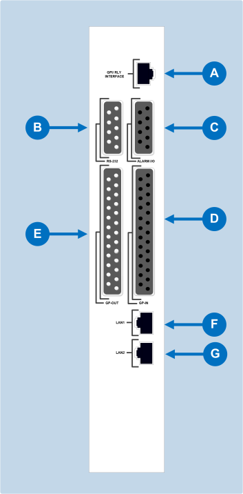
GPI/RLY Interface Connector The RJ-45 socket labeled GPI/RLY Interface connects the CPU card to a GPI-6 or RLY-6 card. The GPI-6 provides six general-purpose opto-isolated logic inputs. The RLY-6 card provides six single-pole, double-throw relay outputs. Both card types mount in either an IMF-3 interface frame or an IMF-102 interface frame. Up to ten GPI-6 or RLY-6 cards can be operated at one time from the matrix by daisy-chaining the cards together. Each card has an IN and an OUT connector for this purpose. The RLY-6 and GPI-6 cards connect to the GPI/RLY interface connector using shielded category-5 cable. For more information about the GPI-6 and RLY-6 cards, consult their respective manuals in the Eclipse HX documentation set. Clear-Com recommends the use of shielded cable. For wiring pinout information for GPI/RLY interfaces, see the:
|
|
|
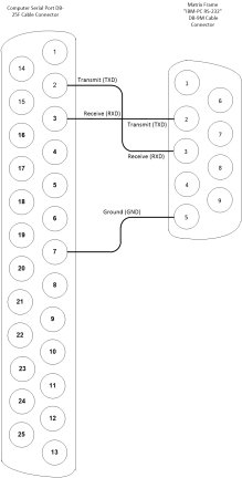
RS-232 DB-9 Connector The DB-9 connector labeled RS-232 connects the Eclipse HX-Delta matrix to an external computer. To connect a computer to the matrix, run cable from the RS-232 connector to the PC’s serial port. The maximum recommended length of the cable is approximately 10 feet (3 meters). A computer has either a 9-pin serial port or a 25-pin serial port.
|
|
|
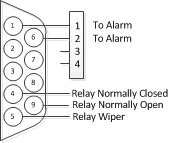
Alarm I/O Connector The DB-9F connector labeled Alarm I/O connects the matrix to a control circuit for an external alarm, such as a light or bell. The external alarm activates whenever an alarm condition is detected in the matrix.
An alarm condition activates the relay contacts connected to pins 4, 5, and 9. These contacts are “dry”, (no voltage is supplied to them by the matrix) and are rated at 1 A at 24 VDC. They should not be used for AC mains line current. Pins are provided for adding an additional alarm source to the matrix’s alarm system. Pin 6 is an alarm input to the Eclipse HX-Delta matrix. It is connected to the input of a 3.3 V logic device. A logic high on this input will cause the Eclipse HX-Delta matrix to detect an alarm condition. A logic low or an open circuit means that the matrix will not detect an alarm condition. Pin 1 is a voltage source out of the Eclipse HX-Delta matrix. It is connected through a 10Kohm pull-up resistor to the +5 V supply rail inside the Eclipse HX-Delta matrix. A contact closure placed across pins 1 and 6 will also cause an alarm condition. Tip: The alarm outputs of the PSU-101 power supply could be wired directly to these pins allowing the CPU card to report PSU failures also.
|
|
|
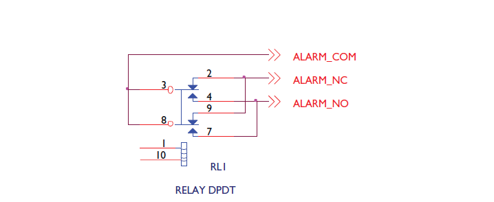
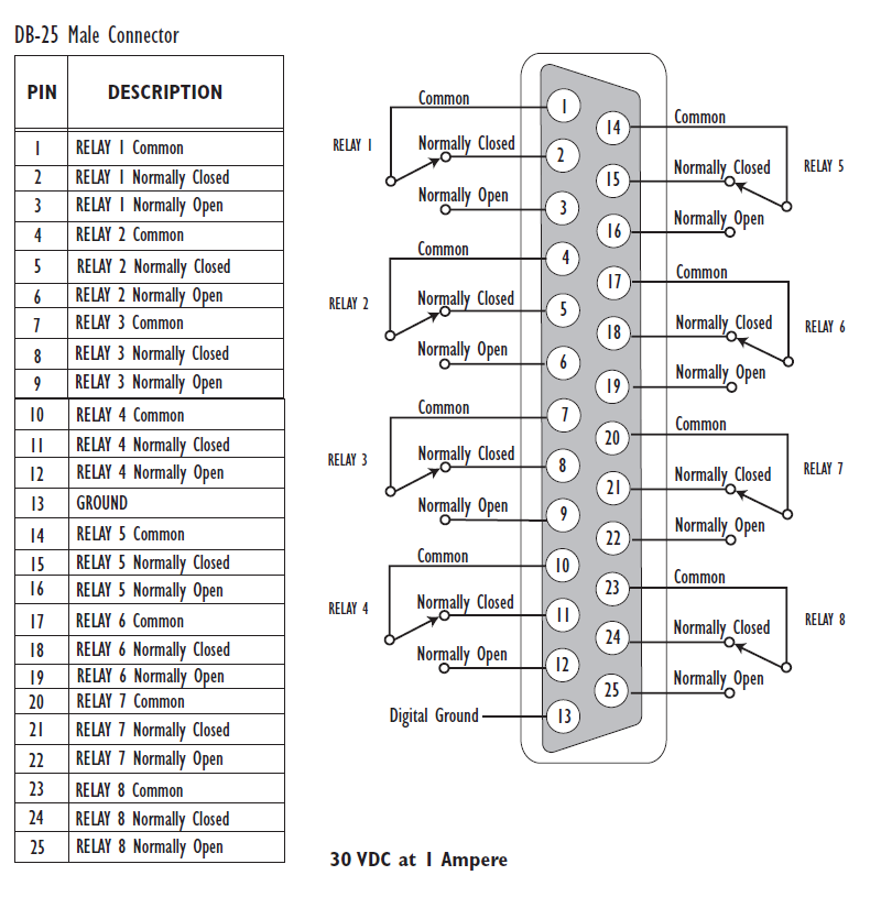
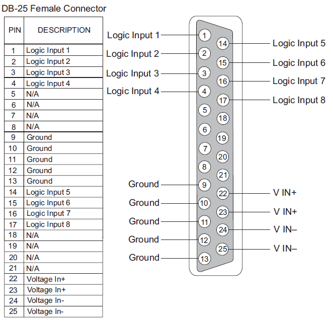
General-Purpose Outputs Connector (GP OUT) A GPO can be programmed to mute a speaker, to turn on an applause light, to turn on a door lock, or to perform a variety of other functions. For example, to get the attention of a panel operator working in a high-noise environment such as a control booth, a relay can be programmed to switch on a light at the operator panel each time an incoming call is received, to ensure that the call is not missed. The DB-25 connector labeled GP OUT connects the matrix to eight double-pole double-throw (DPDT) relays with contact ratings of 30 VDC at 1A. Each general-purpose output has a relay inside the Eclipse HX-Delta matrix. When a general-purpose output is inactive, the associated common pin on the GP OUT connector will be shorted to the relevant normally closed pin. When a general-purpose output becomes active, the short between the common pin is broken and a new connection is made between the common pin and the normally open pin.
|
|
|
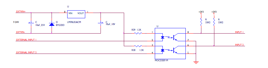
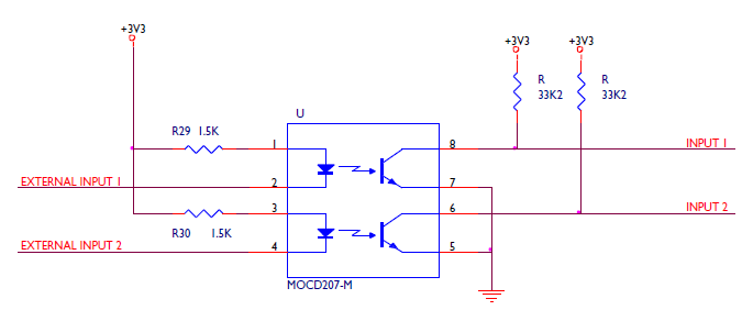
General-Purpose Inputs Connector (GP IN) The DB-25 connector labeled GP IN connects the matrix to eight local general-purpose inputs (GPIs). An external device such as a foot switch, a panel-mounted switch or the logic output of some other device can be connected to the GP IN connector. When the external device is activated, it sends a control signal into the matrix to perform one of several preset functions, such as turning a user panel’s microphone on or off, muting a microphone’s output, or turning a panel’s speaker off. The function to perform and the panel upon which it is performed is configured using EHX. A shielded cable should be used. The general-purpose inputs operate in one of two modes: the opto-isolated mode or the non-isolated mode. The opto-isolated mode requires the externally connected equipment to provide the current to power the general-purpose input. The non-isolated mode does not require that the externally connected equipment powers the general-purpose input. The current is supplied by a voltage output on the GP IN connector. To select a mode, move the J1 jumper on the CPU rear card to one of two positions. The J1 jumper is located on the inner-matrix side of the DB-25 connector. For opto-isolated mode, fit the J1 jumper across pins 1 and 2. For non-isolated mode, fit the J1 jumper across pins 2 and 3. It is recommended that the connector is set to the fully opto-isolated mode. Opto-isolated mode
In this mode, a DC voltage of between 7 and 24 volts is required at the EXTVIN+ pin with relation to the EXTVIN– pin. To cause an input to detect an active signal, current must flow from the relevant input pin. The external device should draw no current to cause an inactive input and at least 5 mA to cause an active input. The opto-isolator drive line contains a 1.5 kOhm resistor to limit the current through the opto-isolator. Therefore, the input pins can be connected directly to the EXTVIN– level to cause an active input. The voltage level at the external input pin should not be allowed to go below EXTVIN– or above +6 V with respect to EXTVIN–. Non-isolated mode To cause an input to detect an active signal in non-isolated mode, the current must flow from the relevant input pin. The external device should draw no current to cause an inactive input and at least 5 mA to cause an active input. The opto-isolator drive line contains a 1.5 kOhm resistor to limit the current through the opto-isolator. Therefore, the input pins can be connected directly to a ground pin to cause an active input. The voltage level at the external input pin should not be allowed to go below ground or above +6 V with respect to ground.
|
|
|
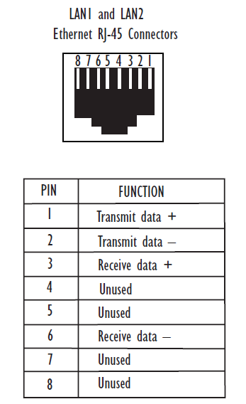
Local Area Network connector (LAN1) The LAN1 and LAN2 connectors have standard Ethernet pin assignments. See G below for pin assignments. The RJ-45 socket labeled LAN 1 connects a local area network (LAN) to the CPU card through a standard Ethernet connection. The green LED indicates the port is connected and the amber LED indicates activity. Clear-Com recommends the use of shielded cable. |
|
|
Local Area Network connector (LAN2) The LAN1 and LAN2 connectors have standard Ethernet pin assignments. The green LED indicates the port is connected and the amber LED indicates activity.
Clear-Com recommends the use of shielded cable. |