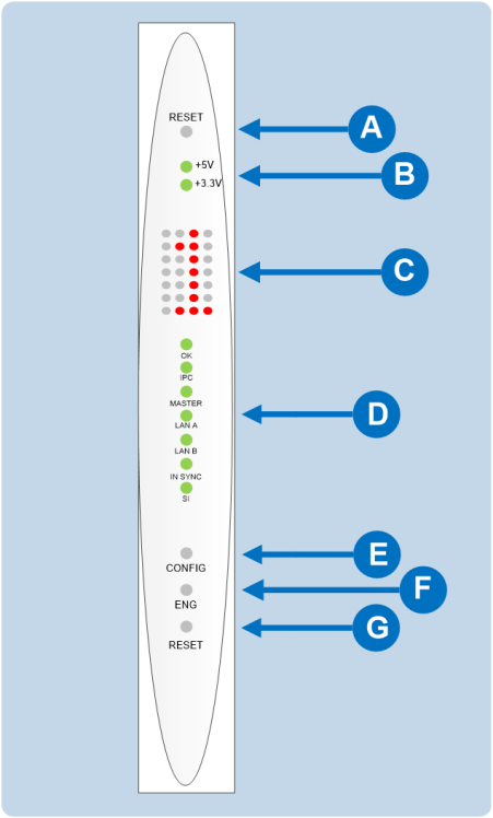
CPU Card Lights and Controls
|
Key to CPU card lights and controls |
|
|---|---|
|
Feature |
Description |
|
|
RESET button Pressing the RESET button causes the CPU card to stop its current activity and to restart. The same configuration that was active before the system was reset will be active after the system was reset. During the reset, configuration information reloads to the card’s operational memory from its non-volatile memory and the card starts running again from the beginning. The reset button is slightly recessed from the front panel to prevent it from being accidentally pressed. A tool such as a bent paper clip is needed to press this button. |
|
|
Power supply lights + 5-Volt light When lit green, the +5V light indicates that the matrix’s +5-volt power supply is actively supplying power to the CPU card. +3.3-Volt light When lit green, the +3.3V light indicates that the matrix’s +3.3-volt power supply is actively supplying power to the CPU card. |
|
|
Dot Matrix lights The rectangular array of lights just below the power-supply lights displays a number (either 1, 2, 3, or 4) to indicate the currently selected configuration. The EHX configuration software controls these lights. In addition, these lights will indicate if the following errors are detected at startup: NVRAM error When the NVRAM is found to be corrupt at start up the config card will output the string CHECK BATTERY. Non matching slave firmware The Eclipse HX system only supports master and slave backup between two cards that are running the same version of firmware. In the case when a non matching slave card firmware version is detected the NON-MATCHING SLAVE_FIRMWARE message is displayed by the master CPU card. Hardware version verification When an older, unsupported version of the MVX or E-QUE FPGA is detected, the EQUE FPGA VERSION USUPPORTED message is displayed by the master CPU card. Note: The dot matrix lights will also display system information when the ENG button is pressed on the master CPU card. This is described below in the section on the ENG button. |
|
|
Status lights OK Light When flashing green, the OK light indicates that the CPU card is successfully communicating with the EHX configuration software. IPC (Interprocessor Communication) Light The Interprocessor Communication (IPC) light only operates when there are two CPU cards in the matrix. When lit green, the light indicates that the two CPU cards are exchanging information. Master Light An Eclipse HX-Delta system can have two CPU cards, although the system will operate with green only one. If the primary card becomes unavailable for any reason, the second card can serve as backup while the primary card is repaired or replaced. The master light is lit on whichever CPU card is currently serving as master. If there is a backup CPU card in the matrix, its “master” light will not illuminate if the primary card is acting as master. LAN A Light When a local area network (LAN) is connected to the matrix’s LAN A port, the CPU card’s LAN A LED is lit green to indicate a connection to the Eclipse Configuration Software LAN A port. LAN B Light When a second local area network is connected to the matrix’s “LAN B” port, the CPU card’s LAN B LED is lit green to indicate a connection to the Eclipse Configuration Software (EHX) LAN B port. Sync Light When multiple Eclipse HX matrices are connected together the Sync light is lit green to indicate that the matrices are connected and synchronized. SI Light The SI light flashes green to indicate communications activity. |
|
|
Configuration [ CONFIG ] button The CPU card can hold four complete system configurations in its operational memory. When the CONFIG button is pressed the number of the currently active configuration (either 1, 2, 3, or 4) appears in the dot-matrix display. Each time the button is subsequently pressed the next configuration number in the series appears in the dot-matrix display. The numbers cycle forward until all of the choices have been displayed, then start again at 1. When a non-active configuration’s number appears in the display, it flashes to indicate its non-active status. When an active configuration’s number (either 1, 2, 3, or 4) appears in the display, it illuminates solidly (without flashing) to indicate that it is the active configuration. To select one of the four configurations from the CPU card:
Note: The CPU card includes an additional, embedded configuration, which can be activated for fast fault checking following a system upgrade or field install. For more information, see the Using the Embedded Configuration section. |
|
|
Engineering [ ENG ] button This button is used to reset the system to the default IP address (169.254.0.10) with DHCP enabled and to display system information on the LED dot matrix (see Setting the Default IP Address). System status If the ENG button only on the master CPU is pressed the following system information will be displayed on the LED dot matrix:
Note: If this address was not statically allocated, but instead was allocated via DHCP server this will be pre-pended by DHCP ENABLED.
|
|
|
Full Reset button When a full reset is performed, all cards in the matrix reset, regardless of any system preferences in the program software. Non-volatile memory is cleared. To perform a full reset:
The CPU card then performs a full reset. The same configuration that was active before the system was reset will be active after reset. When the cards and connected audio devices reset, they momentarily stop their current activity and restart. During this process configuration information is downloaded to the cards and audio devices from the CPU card’s non-volatile RAM. Note: Under normal operating conditions it is not necessary to perform a full reset. Technical personnel might perform a full reset if they believe that the CPU card is operating incorrectly as a result of corruption of the microprocessor’s internal data or instruction sequence. |


