Connecting 4-Wire
When referring to intercoms, a four-wire circuit describes an intercom connection (I/O) where there are four wires (two paths) and the paths are different for talk and listen.
Analog or four-wire circuits use two pairs for balanced line-level audio signals, one for input and the other for output, using four wires in total.
|
Note:
|
A four-wire audio circuit is further defined by the attribute that the two paths can be used for unassociated signals. This means that the source input is not always associated with or routed to the destination output. This is commonly known as a four-wire split or split port. At the time of writing, a split port is only available on Eclipse-HX Digital Matrix products. |
|
Note:
|
To minimize noise and meet regulatory requirements, use screened (shielded) cable when connecting 4-wire ports. |
All Clear-Com four-wire audio ports are analog format line level (0 dBu nominal / 18 dBu max).
When connecting non-Clear-Com equipment to a Clear-Com device, the following is the correct default pinout of the four-wire port (RJ45) for input and output.
|
Note:
|
Except the Eclipse MVX-A16 interface card (input 3 & 6, output 4 & 5). |
| 1 |
n/a |

|
| 2 |
n/a |
| 3 |
Audio Out + |
| 4 |
Audio In + |
| 5 |
Audio In - |
| 6 |
Audio Out - |
| 7 |
n/a |
| 8 |
n/a |
| 1 |
n/a |
|
| 2 |
n/a |
| 3 |
Audio Out + |
| 4 |
Audio In + |
| 5 |
Audio In - |
| 6 |
Audio Out - |
| 7 |
n/a |
| 8 |
n/a |
|
Note:
|
Always read your 3rd party manual before connecting to Clear-Com. |
|
Note:
|
The above diagram illustrates the default pinout mode for Clear-Com RJ45 : 4-wire-X. See Port Function for details. |

|
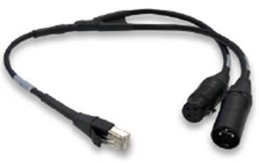
A breakout cable is supplied with the Arcadia and Edge base stations. For other connections you need to make your own cable. |
|
The cable is available to buy from Clear-Com:
CAB-RJ45-PGM-SA - Four-Wire Analog Audio Splitter Cable - PGM/SA with RJ45 to 3-pin XLR-F & 3-pin XLR-M.
|
