Wiring Schemes for the CCI-22 Interface Module
The CCI-22 interface module connects two 2-wire full-duplex partyline circuits to the matrix .
In the same way as the FOR-22, the CCI-22 dual audio interface module uses both the RJ-45 connectors on its rear panel for connection to the matrix (See also the Wiring Schemes for the FOR-22 Interface Module section.
The top RJ-45 is for the first channel of the interface. The lower RJ-45 is for the second channel. The DB-9Ms are the interface module’s audio and control inputs and outputs.
| Note: | For more information about the CCI-22 interface, see the CCI-22 Manual. |
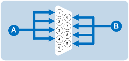
The two DB-9M connectors are paralleled such that both partyline channels are available on each connector. It is possible to:
-
Wire one DB-9 connector as Channel #1 and the second DB-9 as Channel #2.
-
Bring both channels out either DB connector together to create a TW-type partyline connection.
|
DB-9M interface I/O connector for CCI-22 |
|
|---|---|
|
Connector |
Description |
|
|
Channel #1: Pin 1 = Clear-Com / RTS Pin 2 = Ground Pin 3 = +30 VDC Power Pin 4 = Audio |
|
|
Channel #2: Pin 6 = Clear-Com / RTS Pin 7 = Ground Pin 8 = + 30 VDC Power Pin 9 = Audio |


Stations on Clear-Com analog partyline systems (such as Encore) connect to each other with two-conductor shielded microphone cable.
One conductor carries the DC power (28 to 30 V) for that channel, while the other conductor carries the duplex two-way intercom audio signal plus DC Call Light signaling for that channel. The shield acts as common ground for both power and signal for the channel.
Powering the CCI-22 interface module
Power to the CCI-22 interface module channels is provided by the external partyline.
The power connection for each channel is the +30 VDC Power pin on the appropriate DB-9M interface I/O connector on the rear-panel assembly. The CCI-22 channel is essentially just another beltpack on the partyline.
The power pin has DC filtering circuitry that provides a high impedance for the audio such that power can be received from a powered line or TW line, as is common with RTS systems. For TW operation tie the AUDIO and POWER pins together.
Terminating the partyline channels
Each partyline channel requires exactly one termination circuit. The termination circuit is usually built into the system component that provides the party line’s power. Connecting more than one termination circuit to a party line will impair the sidetone null and degrade the line’s audio quality.
Important note:
When a CCI-22 partyline channel is connected to a Clear-Com partyline, the Clear-Com/RTS Select pin must be left floating.
Grounding this pin selects the RTS mode, which is incompatible with Clear-Com partylines.