Wiring Schemes for a GPI-6 Interface Module
The GPI-6 input interface module provides connection for six programmable inputs to the matrix so that each input can control a predefined matrix function.
Multiple GPI-6 interfaces can be daisy-chained to provide connection of up to 60 inputs to the matrix. RLY-6 and GPI-6 modules can be mixed together up to the total limit of 60 items.
Five RLY-6 and five GPI-6 modules would provide 30 relays and 30 inputs for a total of 60 inputs and outputs.
| Note: | If both GPI-6 and RLY-6 interface modules are used, the GPI-6 interface modules must be placed first in the daisy chain. |
Wiring the GPI-6 to the IMF-3 interface frame
To connect the GPI-6 to the matrix:
-
Connect one end of an RJ-45 cable (eight wires with no reversal) into the GPI/RLY INTERFACE connector on the back of the frame.
-
Connect the other end into the top RJ-45 (CH. A MATRIX) connector for the GPI-6.
To connect an additional GPI-6 Interface module:
-
Connect one end of a short RJ-45 cable into the lower RJ-45 (CH. B MATRIX) for the first GPI-6.
-
Connect the other end of the cable into the top RJ-45 (CH. A MATRIX) connector for the additional GPI-6.
Additional GPI-6 Interface modules are added in the same way, using daisy-chain wiring. If there are multiple GPI-6 modules used, the inputs in the first will be numbered 1 to 6, second will be 7 to 12, etc.
RLY-6 modules can be mixed in this daisy-chained scheme. The maximum combined length of all the RJ-45 cables should not exceed 20ft. (6m).
Wiring the GPI-6 to external devices
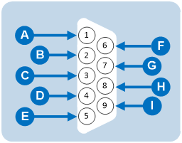
To connect external devices to the GPI-6 interface, use the two DB-9M connectors on the rear cable assembly panel for the interface.
The image below shows the pin assignment of these connectors as viewed from the frame side of the connector.
| Notes: | If a DB-9F is plugged into the connector labeled CH. A I/O, inputs 1 to 3 are available on that connector. |
| The connector labeled CH. B I/O has inputs 4 to 6. In the image below, the labels on the pins apply to either connector. |
|
GPI-6 DB-9M connector pinout |
|
|---|---|
|
Connector |
Description |
|
|
#1/4 Input A |
|
|
#2/5 Input A |
|
|
#3/6 Input A |
|
|
Ground |
|
|
Ground |
|
|
#1/4 Input B |
|
|
#2/5 Input B |
|
|
#3/6 Input B |
|
|
Power source |


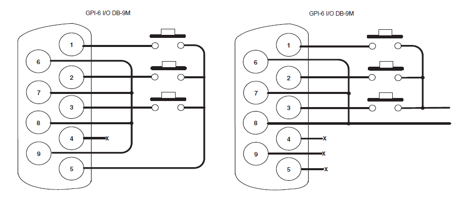
The image above shows you how to connect switches or contacts using the power source provided by the GPI-6 module or powering switches from external sources. Each input can be wired to be isolated from each other as a further variation.
Wiring the GPI-6 to an IMF-102 interface frame
The wiring of a GPI-6 interface that is placed in an IMF-102 interface frame is the same as the wiring for a GPI-6 interface placed in an IMF-3 interface frame.
The only difference is that an IMF-102 interface frame houses only two interfaces, and they are mounted horizontally rather than vertically in the frame.
| Note: | The IMF-3 rear panel and IMF-102 rear panel images show the differences between these interface frames. |
For more information, see your IMF-102 and IMF-3 documentation.
| Note: | To define an input function, use the EHX configuration software (see your EHXdocumentation and EHX Help. |