Wiring Schemes for TEL-14 Interface Modules
The TEL-14 telephone interface module connects two telephone lines to the matrix. The interface can be used to:
-
Establish IFB connections between the main intercom and remote production trucks.
-
Link intercom communication between remote systems.
-
Enable telephone calls directly to or from any intercom panel in an Eclipse system.
The TEL-14 uses each of the RJ-45 connectors on its rear panel for connection to a matrix port. One RJ-45 is for Line A of the interface and the other RJ-45 is for Line B of the interface.
The DB-9M connectors are the Line A and Line B connections to the telephone line. Clear-Com provides DB-9F to RJ-11 adapters so that standard phone line RJ-11 plugs and jacks can connect directly to the interface.
| Note: | For more information about the TEL-14 interface module, see the TEL-14 Manual. |
Wiring the TEL-14 interface to an IMF-3 interface frame
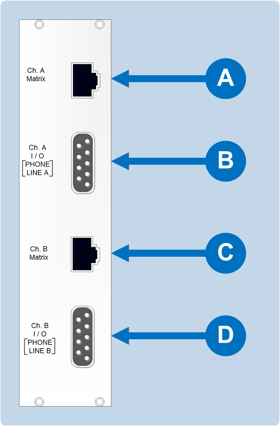
On the rear of the IMF-3 frame, there is a separate rear-panel assembly for each interface module, which contains four connectors for each interface.
|
Wiring an IMF-3 rear panel to a TEL-14 interface module |
|
|---|---|
|
Connector |
Instruction / description |
|
|
The upper DB-9M connector is used to connect to the first telephone line, line A. |
|
|
The upper RJ-45 connector is then used to connect telephone line A to the matrix. |
|
|
The lower DB-9M connector is used to connect to the second telephone line, line B. |
|
|
The lower RJ-45 connector is used to connect telephone line B to the matrix. |


| Note: | To allow use of a common RJ-11 terminated telephone line, Clear-Com provides two DB-9F to RJ-11 adapters (Clear-Com part 770025). |
For internal dip-switch settings and adjustments, see the TEL-14 Manual.
Wiring a TEL-14 interface to an IMF-102 interface frame
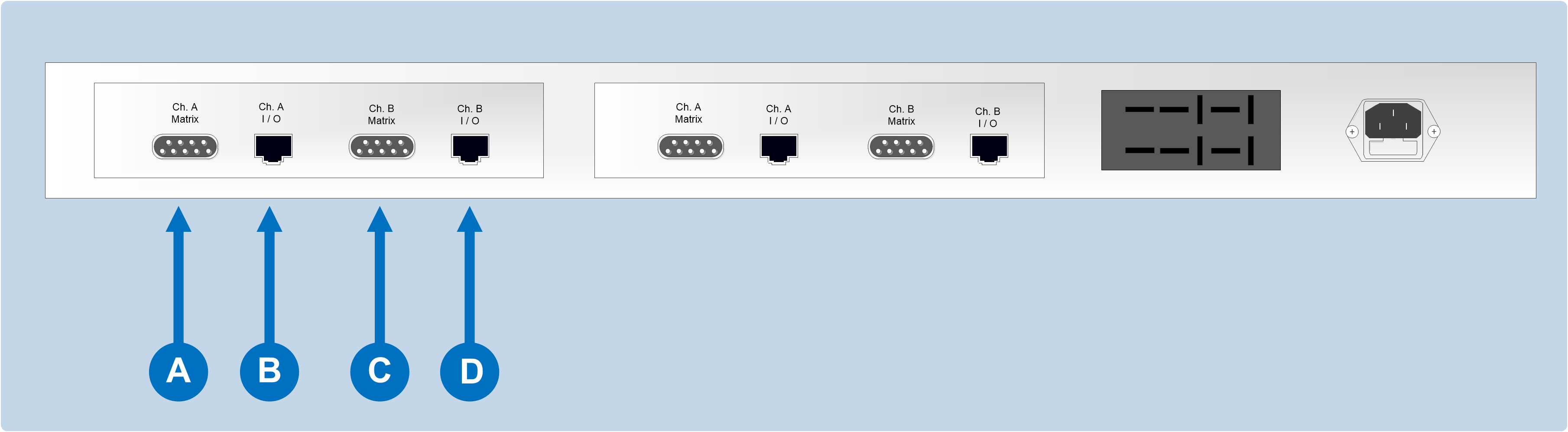
On the rear of the IMF-102, there are two sets of four connectors each, arranged horizontally.
|
Wiring an IMF-102 rear panel to a TEL-14 interface module |
|
|---|---|
|
Connector |
Instruction / description |
|
|
DB-9M connector. Connects to the first telephone line, line A. |
|
|
RJ-45 connector. Connects telephone line A to the matrix. |
|
|
DB-9M connector. Connects to the second telephone line, line B. |
|
|
RJ-45 connector. Connects telephone line B to the matrix. |
| Note: | To allow use of a common RJ-11 terminated telephone line, Clear-Com provides two DB-9F to RJ-11 adapters (Clear-Com part 770025) |
For internal dip-switch settings and adjustments, see the TEL-14 Manual.
Connecting a TEL-14 interface to the telephone line
Connecting the telephone line can be accomplished with one of two methods:
-
Use the RJ-11 to DB-9F adapters supplied by Clear-Com with the TEL-14 interface module.
-
Directly wire each telephone line to a DB-9F connector using the pinouts as shown in the following figure (which displays the wiring diagram of the RJ-11 to DB-9F adapter).
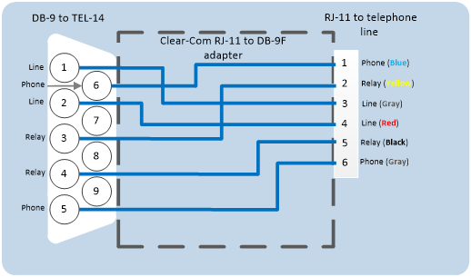
| Note: | The TEL-14 interface works with telephone company central office (CO) lines. Analog panel lines from some in-house PABXs are not compatible. |
Using series-connected telephone sets with the TEL-14
Although it is possible to use a parallel-connected telephone set to originate calls, it is preferable to use a series-connected telephone set with the TEL-14. This prevents the impedance of the telephone set from disturbing the telephone line impedance recognized by the TEL-14.
It will also allow the TEL-14 to automatically disconnect the telephone when it comes “off-hook.” A standard telephone may be installed in series with the TEL-14 by connecting it to pins 1 and 6 of the RJ-11 jack. If telephones must be connected in parallel with the telephone line(s) during the TEL-14’s automatic nulling process, all additional standard telephones must be “on-hook”.
Using relay contacts with the TEL-14 interface
A pair of relay contacts for each telephone line rated at 2A at 24 VAC is available on the DB-9 or the RJ-11 of the adapter. This pair of contacts is normally open when the line is “on-hook,” and closes when the interface goes “off-hook”.
These contacts are not connected to any other circuitry inside the interface, and can be used to energize a line-in-use indicator light on a standard multiline phone set, or for any other low-power application.