Auxiliary audio connector
The auxiliary audio connector allows additional audio inputs and outputs to be connected to the panel.
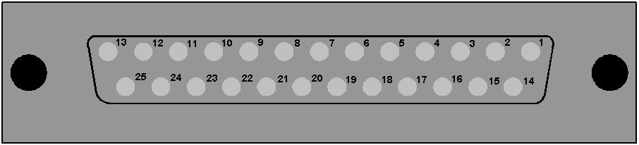
Auxiliary audio connector
| Pin | Description | Pin | Description |
|---|---|---|---|
| 1 | Headset 2 MIC +ve | 14 | Headset 2 MIC -ve |
| 2 | Headset 2 Left Ear | 15 | Headset 2 Left Ear Ground |
| 3 | Headset 2 Right Ear | 16 | Headset 2 Right Ear Ground |
| 4 | Headset 2 PTT 1 | 17 | Headset 2 PTT 2 |
| 5 | 0V | 18 | 0V |
| 6 | 0V | 19 | 0V |
| 7 | External Output 2 +ve | 20 | External Output 2 -ve |
| 8 | External Output 1 +ve | 21 | External Output 1 -ve |
| 9 | Hot MIC Output +ve | 22 | Hot MIC Output -ve |
| 10 | Auxiliary Loudspeaker Output +ve | 23 | Auxiliary Loudspeaker Output -ve |
| 11 | External Input 2 +ve | 24 | External Input 2 -ve |
| 12 | External Input 1 +ve | 25 | External Input 1 -ve |
| 13 | 0V | - | - |
Auxiliary audio connector pinout
| Note: | When wiring headset 2 to use the auxiliary audio connector, Clear-Com recommends using good quality headphone cable to avoid pickup of electronic noise by the microphone connection. |
Wire the Headset 2 PTTs (pins 4 and 17) so that PTT connects the pin to ground.
The auxiliary loudspeaker output is at line levels, and auxiliary loudspeakers cannot be connected directly. Auxiliary loudspeakers must be driven through a suitable audio amplifier. The line output levels are given in the product specifications.