Headset connectors
The headset connector may be one of three types: XLR-4M, XLR-5F or XLR-7M.
The pinouts for each type are shown below.
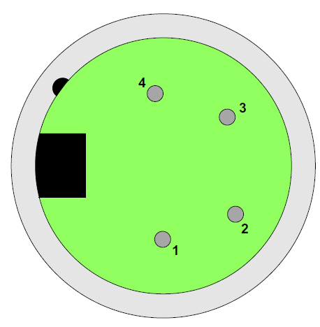
XLR-4M microphone connector
| Pin | Description |
|---|---|
| 1 | Microphone Screen |
| 2 | Microphone Input |
| 3 | Headphone Return |
| 4 | Headphone Output |
XLR-4M headset connector pinout
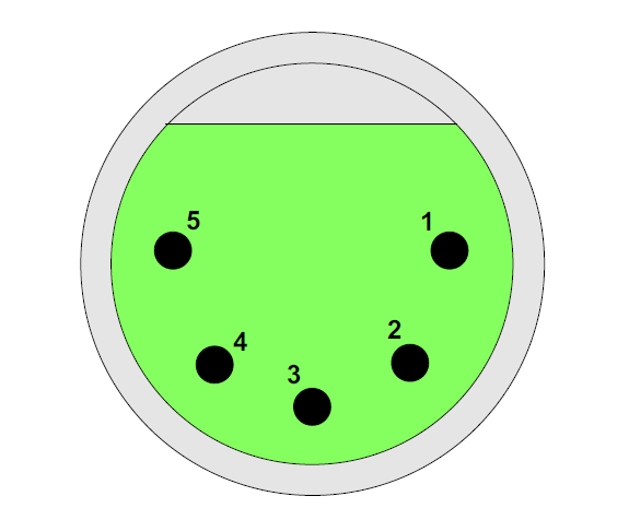
XLR-5F microphone connector
| Pin | Description |
|---|---|
| 1 | Microphone Screen |
| 2 | Microphone Input |
| 3 | Headphone Return |
| 4 | Left Headphone Output |
| 5 | Right Headphone Output |
XLR-5F headset connector pinout
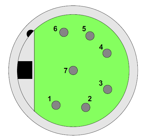
XLR-7M microphone connector
| Pin | Description |
|---|---|
| 1 | Microphone -ve |
| 2 | Microphone +ve |
| 3 | Ground |
| 4 | Left Headphone Output |
| 5 | Right Headphone Output |
| 6 | PTT1 |
| 7 | PTT2 |
XLR-7M headset connector pinout
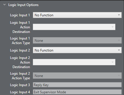
The V-Series panels have two GPI inputs called logic 1 and logic 2. They can be used for PTT actions or wired to foot-switches for example.
The logic 1 can be physically accessed via the rear DB25 socket labelled GPIO connector OR the XLR 7 front headset socket. Both inputs are wired in parallel
The logic 2 can be physically accessed via the rear DB25 socket labelled GPIO connector OR the XLR 7 front headset socket. Both inputs are wired in parallel
They are configured in the EHX software as follows:
1) Select Hardware > Cards and Ports.
2) Select the required port.
3) Select Logic Input Options.
Configuration of the wrong type of microphone or headset will degrade or nullify the audio from the panel or worse still, damage the microphone or headset.
The PTT1 and PTT2 functions on an XLR-7 headset or a second headset connected via the auxiliary audio connector are connected to the logic 1 and logic 2 inputs in the EHX Configuration software (Cards and Ports).
Headset 1 PTT 1 or headset 2 PTT 1 active will have the same effect as Logic 1 active.
Headset 1 PTT 2 or headset 2 PTT 2 active will have the same effect as Logic 2 active.
PTT is activated by grounding the PTT line.