Matrix panel GPIO connector wiring
Most input/output devices (other than the matrix, expansion panels and auxiliary audio devices) are connected to the panel via the GPIO connector. This connector is also used to connect up to two channels over IP.
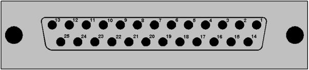
Matrix to panel GPIO connector
| Pin | Description | Pin | Description |
|---|---|---|---|
| 1 | Panel Mute relay output Normally Closed | 14 | Panel Mute output relay Common |
| 2 | Panel Mute relay output Normally Open | 15 | Panel Aux output relay Normally Closed |
| 3 | Panel Aux output relay Common | 16 | Panel Aux output relay Normally Open |
| 4 | Not connected | 17 | Not connected |
| 5 | Not connected | 18 | Not connected |
| 6 | Not connected | 19 | Not connected |
| 7 | Not connected | 20 | 5V |
| 8 | 0V | 21 | 5V |
| 9 | 0V | 22 | Opto-isolated input A1 |
| 10 | Opto-isolated input B1 | 23 | Opto-isolated input A2 |
| 11 | Opto-isolated input B2 | 24 | Opto-isolated input A3 |
| 12 | Opto-isolated input B3 | 25 | Opto-isolated input A4 |
| 13 | Opto-isolated input B4 | - | - |
Matrix to panel GPIP connector pinouts
| Note: | The Relay 1 and 2 outputs on the GPIO connector are referred to in EHX Controls as Panel mute relays and Panel AUX relays respectively. |